
Introduction to IBM Storage Scale and Storage Scale System

Published: 22 September 2026

Abstract

This IBM Redbooks publication provides a comprehensive introduction to the IBM Storage Scale System family of integrated hardware and software storage solutions. Built on IBM Storage Scale technology, the IBM Storage Scale System delivers high-performance, reliable file and object storage designed for AI, high-performance computing (HPC), analytics, and hybrid cloud workloads.

The publication covers the IBM Storage Scale System 6000 and 3500 product lines, describing their architecture, hardware components, software stack, and deployment models. It explains how IBM Storage Scale System functions as a scalable storage building block within an IBM Storage Scale cluster, supporting massive scalability, software-defined RAID with de-clustered erasure coding, and flexible network connectivity including 100/200/400 Gb Ethernet and InfiniBand HDR/NDR.

Authors

Phillip Gerrard, Sagrika Arora, Nilton Carlos Dos-Santos, Jordi Caubet, Michael Kieran, Stieg Klein, Chris Maestas and Bis Purkayastha

  • IBM Storage Scale System models
    • IBM Storage Scale System model specifications
    • IBM Storage Scale RAID technical overview

IBM Storage Scale System models

This section includes the differences between the three generations of IBM Storage Scale Systems (IBM Storage Scale System) that are used today. Understanding the nomenclature and the differences between these generations is helpful when you are designing your IBM Storage Scale System environment, especially if different generations of IBM Storage Scale System coexist in the same IBM Storage Scale cluster.

IBM Storage Scale System model specifications

IBM Storage Scale System 6000 specifications

The specifications of the IBM Storage Scale System 6000 model are listed in the following table.

IBM Storage Scale System ModelEnclosure U/Number drives IBM machine type - modelDrive CountDrive sizeIBM Storage Scale System 60004U48 Machine type 5149-F4824 or 483.84 TB 2.5 Inch PCIe Gen4 NVMe Flash Drive 7.68 TB 2.5 Inch PCIe Gen4 NVMe Flash Drive 15.36 TB 2.5 Inch PCIe Gen4 NVMe Flash Drive 30.72 TB 2.5 Inch PCIe Gen4 NVMe Flash Drive 19.2TBu NVMe FlashCore Module 38.4TBu NVMe FlashCore Module 3.84 TB U.3 PCIe 5.0 NVMe SSD 7.68 TB U.3 PCIe 5.0 NVMe SSD 15.36 TB U.3 PCIe 5.0 NVMe SSD 30.72 TB U.3 PCIe 5.0 NVMe SSD 30.72 TB 2.5 Inch QLC NVMe SSD 61.44 TB 2.5 Inch QLC NVMe SSD 122 TB 2.5 Inch QLC NVMe SSD

Front view of the IBM Storage Scale System 6000 fully populated with 24 triple-level cell (TLC) and 24 quad-level cell (QLC) drives. The 4U48 enclosure shows two rows of 24 drive slots each. Colour-coded callout labels identify drive placement: in the top row, QLC drives (green highlight) are in odd-numbered slots and TLC drives (yellow highlight) are in even-numbered slots; in the bottom row, TLC drives (yellow highlight) are in odd-numbered slots and QLC drives (green highlight) are in even-numbered slots.
Figure: IBM Storage Scale System 6000 fully populated with 24 TLC and 24 QLC drives

Front view of the IBM Storage Scale System 6000 fully populated with 12 TLC and 36 QLC drives. The 4U48 enclosure shows two rows of 24 drive slots. Colour-coded callout labels show the specific slot assignments: in the top row, QLC drives (green highlight) occupy slots 1–7, 9, 11, 13, 15, 17, and 19–24, while TLC drives (yellow highlight) occupy slots 8, 10, 12, 14, 16, and 18. In the bottom row, QLC drives (green highlight) occupy slots 25–30, 32, 34, 36, 38, 40, and 42–48, while TLC drives (yellow highlight) occupy slots 31, 33, 35, 37, 39, and 41.
Figure: IBM Storage Scale System 6000 fully populated with 12 TLC and 36 QLC drives

Back panel connection diagram for the IBM Storage Scale System 6000 showing two hardware units: the 5149-23E EMS management server (top) and the 5149-F48 6000 I/O canister pair (bottom), both connected to a Solution management switch at the top. Colour-coded lines show five connection types: blue lines for management network, yellow lines for management/BMC network, orange line for Cluster, purple dashed line for Campus, and red dashed lines for SSR service connections. The left side labels identify the vertical cable runs as BMC network, Management network, and Management/BMC network.
Figure: IBM Storage Scale System 6000 back panel view and connections

IBM Storage Scale System 3500 specifications

The IBM Storage Scale System 3500 is one of the third-generation IBM Storage Scale System offerings.

The IBM Storage Scale System 3500 model includes NVMe flash storage.

The specifications of the IBM Storage Scale System 3500 model are listed in the following table.

IBM Storage Scale System modelEnclosure U/Number drives IBM Machine Type - ModelNVMe drivesDrive sizeIBM Storage Scale System 3500 or IBM Storage Scale System 3500 H02U24 Machine type 5141-FN2NVMe 12 or 243.84 TB 7.68 TB 15.36 TB 30.72 TB

Rear panel connection diagram for the IBM Storage Scale System 3500 showing two hardware units: the 5149-23E EMS management server (top) and the ESS 3500 I/O server pair (bottom), both connected to a Solution management switch at the top. Colour-coded lines show four connection types: blue lines for management network, yellow lines for BMC network, green lines for BMC network on the ESS 3500, and red lines for SSR service connections (via adapter on the ESS 3500). A purple line connects the EMS to a Campus network port. Vertical labels on the left identify the cable runs as BMC network, Management network, and BMC network.
Figure: IBM Storage Scale System 3500 rear panel view and connections

The IBM Storage Scale System 3500Hx, shown in the following table, includes machine type 5141-FN2 and 1-4 model 5147-102.

IBM Storage Scale System ModelEnclosure U/Number drives IBM machine type - modelNVMeHDD enclosureHDD drivesDrive sizeIBM Storage Scale System 3500H12U24 Machine type 5141-FN2 + 1@4U external storage Model 5147-102Quantity: 12 or 24 Size: 3.84 TB 7.68 TB 15.36 TB 30.72 TB152 or 102HDD: 10 TB, 14 TB, 18 TB, 20 TB, 22 TB 24 TB3500H22U 5141-FN2 + 2@4U 5147-102Quantity: 12 or 24 Size: 3.84 TB 7.68 TB 15.36 TB 30.72 TB2204HDD: 10 TB, 14 TB, 18 TB, 20 TB, 22 TB 24 TB3500H32U 5141-FN2 + 3@4U 5147-102Quantity: 12 or 24 Size: 3.84 TB 7.68 TB 15.36 TB 30.72 TB3306HDD: 10 TB, 14 TB, 18 TB, 20 TB, 22 TB 24 TB3500H42U 5141-FN2 + 4@4U 5147-102Quantity: 12 or 24 Size: 3.84 TB 7.68 TB 15.36 TB 30.72 TB4408HDD: 10 TB, 14 TB, 18 TB, 20 TB, 22 TB 24 TB3500H52U 5141-FN2 + 5@4U 5147-102Quantity: 12 or 24 Size: 3.84 TB 7.68 TB 15.36 TB 30.72 TB5510HDD: 10 TB, 14 TB, 18 TB, 20 TB, 22 TB 24 TB3500H62U 5141-FN2 + 6@4U 5147-102Quantity: 12 or 24 Size: 3.84 TB 7.68 TB 15.36 TB 30.72 TB6612HDD: 10 TB, 14 TB, 18 TB, 20 TB, 22 TB 24 TB3500H72U 5141-FN2 + 7@4U 5147-102Quantity: 12 or 24 Size: 3.84 TB 7.68 TB 15.36 TB 30.72 TB7714HDD: 10 TB, 14 TB, 18 TB, 20 TB, 22 TB 24 TB3500H82U 5141-FN2 + 8@4U 5147-102Quantity: 12 or 24 Size: 3.84 TB 7.68 TB 15.36 TB 30.72 TB8816HDD: 10 TB, 14 TB, 18 TB, 20 TB, 22 TB 24 TB

The IBM Storage Scale System 3500Cx, shown in the following table, includes machine type 5141-FN2 logtip only NVMe drives and 1—8 model 5147-102 enclosures.

IBM Storage Scale System ModelEnclosure U/Number drives IBM machine type - modelNVMeHDD enclosureHDD drivesHDD Drive sizeIBM Storage Scale System 3500C12U24 Machine type 5141-FN2 + 1@4U external storage Model 5147-102Quantity: 4 (used for logtip)152 or 10210 TB, 14 TB, 18 TB, 20 TB, 22 TB 24 TB3500C22U 5141-FN2 + 2@4U 5147-102Quantity: 4 (used for logtip)220410 TB, 14 TB, 18 TB, 20 TB, 22 TB 24 TB3500C32U 5141-FN2 + 3@4U 5147-102Quantity: 4 (used for logtip)330610 TB, 14 TB, 18 TB, 20 TB, 22 TB 24 TB3500C42U 5141-FN2 + 4@4U 5147-102Quantity: 4 (used for logtip)440810 TB, 14 TB, 18 TB, 20 TB, 22 TB 24 TB3500C52U 5141-FN2 + 5@4U 5147-102Quantity: 4 (used for logtip)551010 TB, 14 TB, 18 TB, 20 TB, 22 TB 24 TB3500C62U 5141-FN2 + 6@4U 5147-102Quantity: 4 (used for logtip)661210 TB, 14 TB, 18 TB, 20 TB, 22 TB 24 TB3500C72U 5141-FN2 + 7@4U 5147-102Quantity: 4 (used for logtip)771410 TB, 14 TB, 18 TB, 20 TB, 22 TB 24 TB3500C82U 5141-FN2 + 8@4U 5147-102Quantity: 4 (used for logtip)881610 TB, 14 TB, 18 TB, 20 TB, 22 TB 24 TB

IBM Storage Scale RAID technical overview

The following section provides a high-level, technical overview of the IBM Storage Scale RAID that is used in all IBM Storage Scale System models.

The IBM Storage Scale RAID software that is used in the IBM Storage Scale System solution runs on SAS disks in just a bunch of disks (JBOD) arrays. IBM Storage Scale RAID on IBM Storage Scale System provides JBOD cost reduction while simultaneously providing enterprise class reliability.

Different IBM Storage Scale System models provide solid-state drives (SSDs or NVMe) when more performance is needed. The IBM Storage Scale System solution does not require or use any external RAID controller or acceleration.

IBM Storage Scale RAID supports multiple RAID codes and distributes client data, redundancy information, and spare space across the disks in such a way that if a physical disk loss or even a group of physical disk loss occurs, it does not affect data availability.

Instead of relying on the disks or conventional RAID controller only, IBM Storage Scale RAID implements erasure coding, which is embedded within the IBM Storage Scale file system to provide reliability and high performance. This configuration detects and reports storage media faults and read or write errors, and resolves other data integrity problems.

IBM Storage Scale RAID also implements an end-to-end checksum from the storage media all the way out to the IBM Storage Scale client.

IBM Storage Scale RAID erasure codes

IBM Storage Scale RAID in the IBM Storage Scale System supports different data protection algorithms and can detect and correct up to two or three concurrent storage media faults per erasure code array.

IBM Storage Scale RAID diagram showing four code configurations arranged in two rows. Top row (2-fault-tolerant codes): 8+2p Reed-Solomon code illustrated as 8 blue data strips plus 2 beige parity strips; and 3-way replication (1+2) illustrated as 1 blue data strip plus 2 beige replica strips. Bottom row (3-fault-tolerant codes): 8+3p Reed-Solomon code illustrated as 8 blue data strips plus 3 beige parity strips; and 4-way replication (1+3) illustrated as 1 blue data strip plus 3 beige replica strips. Labels explain that 8 strips equal one Spectrum Scale block and 2 or 3 generated parity strips, while 1 strip equals one Spectrum Scale block and 2 or 3 generated replicas.
Figure: IBM Storage Scale RAID tracks

End-to-end checksum

If you use the IBM Storage Scale software client to access data on the IBM Storage Scale System, the IBM Storage Scale client is aware if the IBM Storage Scale file system is based on IBM Storage Scale RAID network shared disks. If this configuration is used, an 8-byte checksum is calculated during a write operation, which is appended to the data, and sent over the network to the IBM Storage Scale RAID server. The checksum is verified and then IBM Storage Scale RAID writes the data along with its checksum on the disks and logs the version number on its metadata.

When a read operation is requested, IBM Storage Scale RAID verifies the checksum and version on its metadata. If verification is successful, it sends the data to the client. If verification fails, the data is rebuilt based on parity or replication and then sent to the client along with a newly generated checksum.

The end-to-end checksum feature provides a robust means to prevent and correct silent disk errors or missing disk writes. This feature provides an essential level of reliability to ensure data integrity and prevent file system checks, which ensure reliability and uptime for ever larger petabyte-scale file systems.

Declustered RAID arrays

IBM Storage Scale RAID implements its own data and spare disk layout scheme that reduces overhead and mitigates the performance impact to users when recovering from disk failures. IBM Storage Scale RAID spreads or declusters user data, redundancy information, and spare space across all the disks of the array instead of leaving all spare space in a single disk. A conventional 1+1 RAID layout is compared to a declustered array in the following figure.
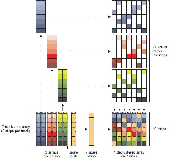
IBM Storage Scale RAID declustered array diagram showing the reorganisation of data from 3 conventional arrays on 6 disks (with 7 tracks per array and 2 strips per track) plus a spare disk with 7 spare strips, into a single declustered array on 7 disks containing 49 strips. On the right side, three colour-coded grid representations show 21 virtual tracks (42 strips) mapped across the 7 disks of the declustered array. Arrows connect each of the three original arrays to their corresponding virtual track grids in the declustered layout, illustrating how data, parity, and spare space are distributed evenly across all disks.
Figure: Declustered array versus a 1+1 array

Consider an example where seven stripes of data are on each disk. The declustered array diagram above shows the left three arrays of two disks in a replicated 1+1 configuration and a spare. On the left, you can see the data stripes spreading all over the seven disks of the declustered array.

In a failure of one disk, all data from the remaining disks of the array must be replicated to the spare disk on the traditional 1+1 array. On the declustered array, the replication occurs on spare space of all the remaining disks, which can decrease the rebuild impact from three to four times.

The IBM Storage Scale RAID overhead reduction is shown in the following figure.
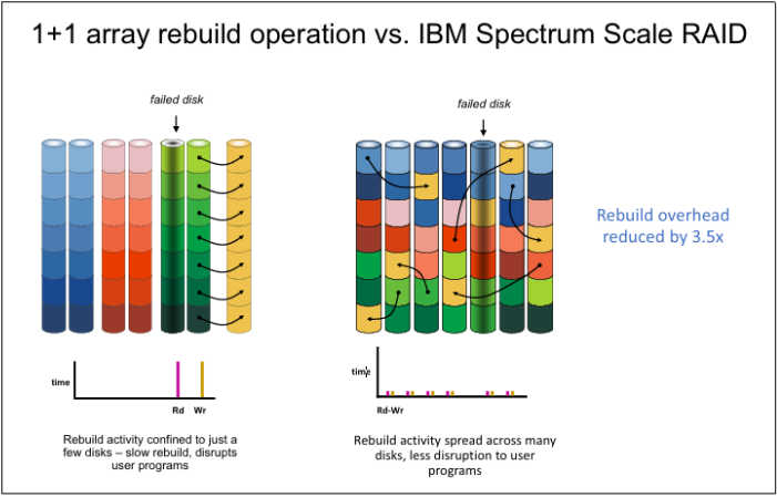
Comparison diagram titled "1+1 array rebuild operation vs. IBM Spectrum Scale RAID" showing two side-by-side illustrations. On the left, a 1+1 conventional array with a failed disk (indicated by a downward arrow) shows rebuild arrows concentrating on just a few disks, with a time graph below showing a single tall pink read spike (Rd) and a yellow write spike (Wr), and a caption reading "Rebuild activity confined to just a few disks – slow rebuild, disrupts user programs". On the right, an IBM Spectrum Scale RAID declustered array with the same failed-disk scenario shows rebuild arrows spreading across all remaining disks, with a time graph below showing many small, evenly distributed coloured spikes labelled "Rd-Wr", and a caption reading "Rebuild activity spread across many disks, less disruption to user programs". A label to the right reads "Rebuild overhead reduced by 3.5x".
Figure: Array rebuild operation

On the IBM Storage Scale System, using RAID 8+2 or 2-way replication (1+2), if one disk loss occurs, the rebuild operation starts with low priority with even lower impact for the clients.

With this array configuration, the rebuild is considered critical and run on high priority only if two concurrent disk losses occur.

By using 8+3 RAIDs or 3-way replication (1+3), the rebuild operation becomes critical only if three concurrent disk losses occur in the same declustered array.